Innovative? Rear Controls for a Motorcycle
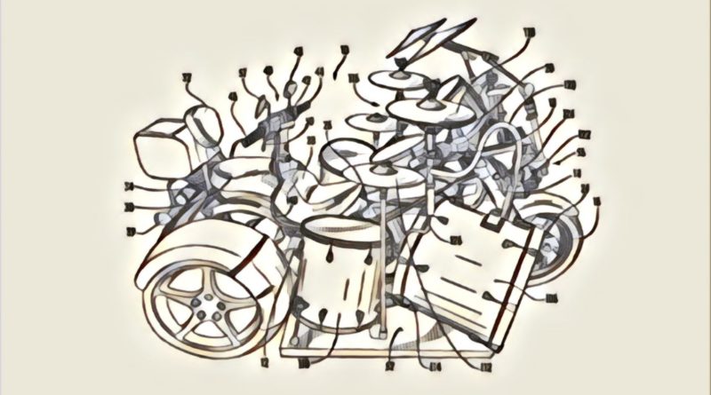
A recently published patent application caught my eye and I saved it in a directory titled “crazy #!#!,” based solely on the drawings in the patent application. Once I had time to go back and read the application I came to the realization that it may not be so crazy after all (if you can get past the drawings of a drum set on a motorcycle).
The patent application published as US Pub. No. 20180141607 with the title “Motorcycle with Rear Controls,” and describes the invention as:
A motorcycle having rear-steering controls, including a rear handle bar for steering, for allowing a rear rider to control the motorcycle from a rearward position.
The application goes on to explain:
[0019] The present invention advantageously provides a motorcycle having at least two wheels with integrated rear motorcycle controls. The present invention contemplates various types of motorcycles with at least two centrally mounted seats with rear motorcycle controls.
[0020] Accordingly, the present invention components have been represented where appropriate by conventional symbols in the drawings, showing only those specific details that are pertinent to understanding the embodiments of the present invention so as not to obscure the disclosure with details that will be readily apparent to those of ordinary skill in the art having the benefit of the description herein.
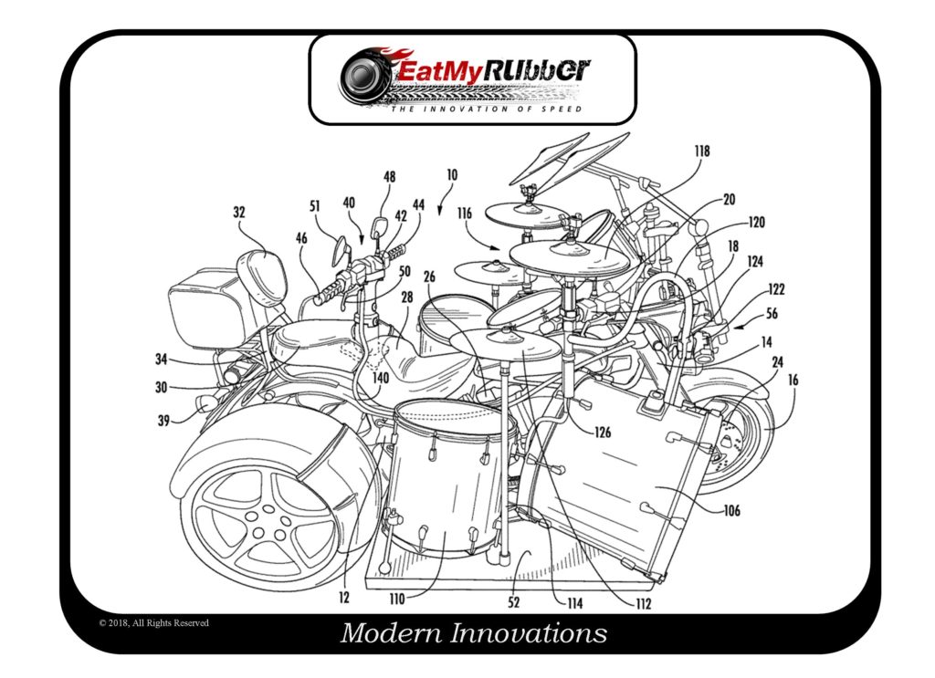
[0021] Referring now to the drawings figures in which like reference designators refer to like elements. FIG. 1 shows an exemplary motorcycle tricycle (hereafter “trike”) with an integrated drum set constructed in accordance with the principles of the present invention and designated generally as trike “10.” In particular, trike 10 includes a three wheel trike frame body 12. The body 12 includes a front trike suspension 14 and a rear trike suspension 36. The front trike suspension 14 carries a steerable front wheel 16.
[0022] Other various conventional motorcycle components are included; for example, a front steering mechanism 18, mirrors 20, fuel tank 22; brakes 24; exhaust 38; brake lights 39. The front steering mechanism 18 includes without limitation handle bars, throttle control, and brake levers for initiating tire braking. The instant invention further includes a conventional engine 26 for propelling the trike 10 forward.
[0023] A front seat 28 and a rear seat 30 are provided centrally mounted in an inline configuration. The rear seat 30 includes a back rest 32. The back rest 32 is supported via a back rest support member 34.
[0024] A rear steering mechanism 40 is provided that controls the position of the steerable front wheel 16. The nonconventional rear steering mechanism 40 includes rear handlebar 42 having dual handgrips 44, 46 for gripping. The handgrips 44, 46 includes padding 51 disposed over at least a portion of the handgrips 44, 46 for the comfort of the rider. One or more rear positioned rear view mirrors 48 coupled with the rear handlebar 42. One or more brake levers 50 are coupled with the handlebar 42 for engaging one or more front brakes 24 and/or rear brakes (not shown) when pressure is applied by the rider to the brake levers 50.
[0025] In one embodiment, the rear steering mechanism 40 is hydraulically driven and/or otherwise coupled to the front trike suspension 14 for controlling the front wheel 16. One or more hydraulic cables 140 secured between the rear steering mechanism 40 and the front trike suspension 14 for turning the front wheel 16. In yet another embodiment, the rear steering mechanism 40 can be used independently of the conventional front handle bars. In one non-limiting embodiment, a switch (not shown) can be adjusted to switch the control of the front wheel 16 between the front steering mechanism 18 and the rear steering mechanism 40.
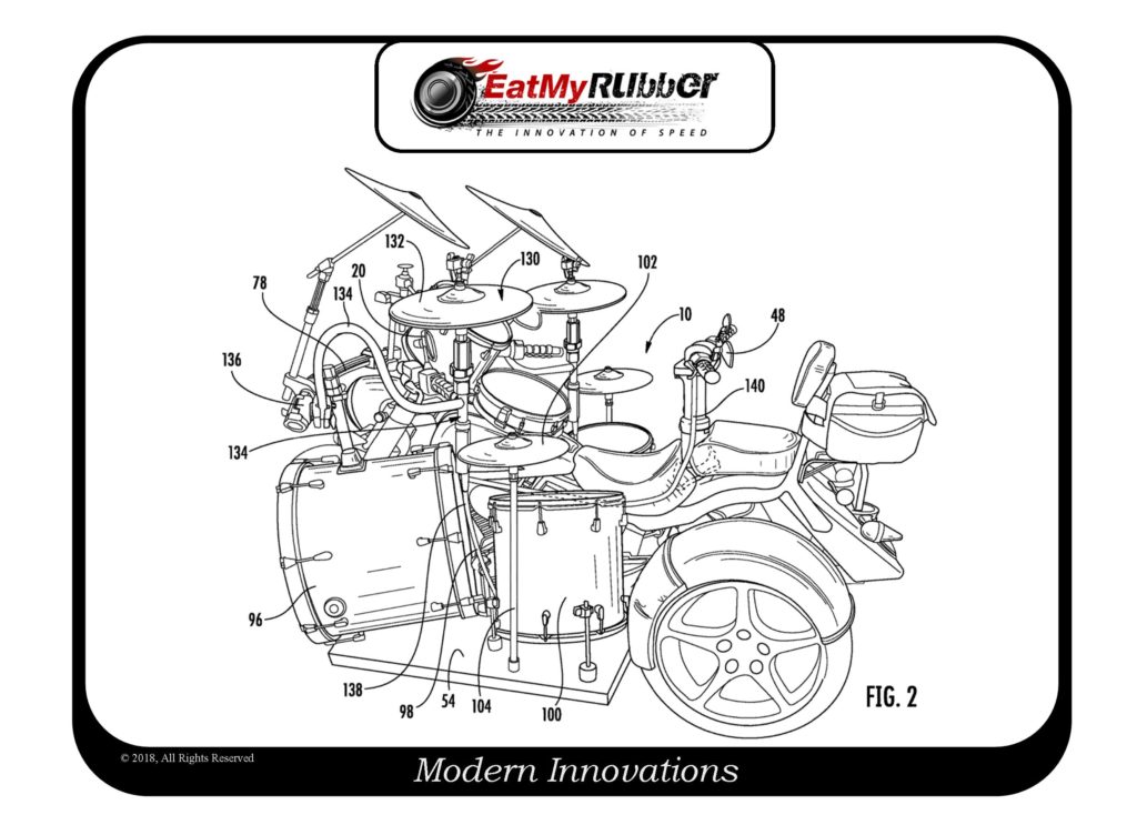
[0026] A right side platform 52 (see FIG. 1) and a left side platform 54 (see FIG. 2) are mounted to the frame body 12. The right and left side platforms 52, 54 should be mounted at a height above the ground to provide the necessary clearance to safely ride the trike on roadways.
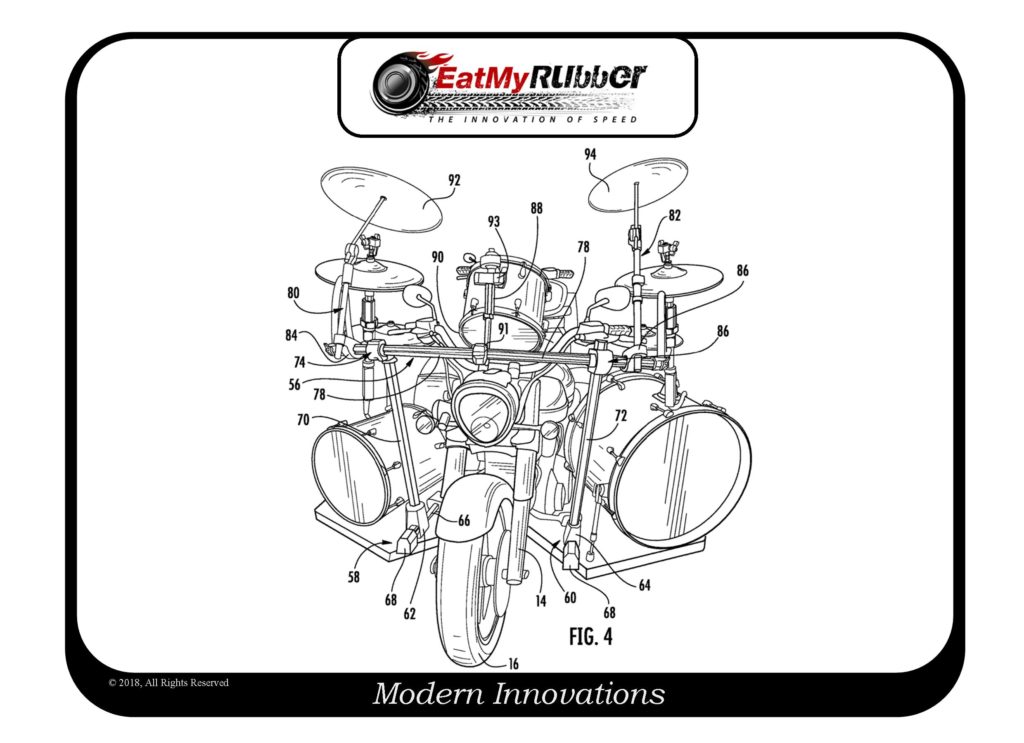
[0027] As illustrated in FIG. 4, a drum rack assembly 56 is mounted on the right and left side platforms 52, 54. The drum rack assembly includes a right t-leg assembly 58 that is mounted with the right side platform 52 and a left t-leg assembly 60 that is mounted with the left side platform 54. Each of the right and left t-leg assemblies 58, 60 include a t-leg clamp 62, 64. The t-leg assemblies 58, 60 each include horizontal leg sections 66 and a plurality of feet 68 for stabilization. A right leg 70 and a left leg 72, each having a first and second end, engage the t-leg assemblies 58, 60 respectively at one end thereof, as illustrated in FIG. 3. The right and left legs each engage horizontal clamp assemblies 74, 76 on their opposite ends.
[0028] A horizontal upper bar 78 is configured to maintain a number of boom arms or other members thereof. The horizontal upper bar 78 is provided as a straight bar, however, a curved bar may be implemented without departing from the spirit and scope of the instant invention. The horizontal upper bar 78 is positioned forward from the handlebars to prevent interference during turning, as illustrated in FIG. 1. A right cymbal boom assembly 80 and a left cymbal boom assembly 82 is coupled on their first end to the horizontal upper bar 78 via a cymbal boom clamp assembly 84, 86. The cymbal boom clamp assemblies 84, 86 prevent the cymbal boom assemblies 80, 82 from sliding about the horizontal upper bar 78 when clampedly engaged. The right and left cymbal boom assemblies 80, 82 are coupled with a cymbal on their opposite ends, 92, 94. While the instant invention shows only one cymbal 92, 94 coupled with the right and left cymbal boom assemblies, additional crash cymbals, or other types of cymbals, may be coupled with the cymbal boom assemblies 80, 82 such that two or more cymbals are secured to each cymbal boom assembly 80, 82.
[0029] A drum boom 88 is coupled to the horizontal upper bar 78 via a drum boom clamp assembly 90 on a first portion 91 and coupled to a drum 144 on a second portion 93. Other arms and booms may be secured to the drum rack assembly 56 as desired or required. The horizontal upper bar 78 is fluted, dovetailed or otherwise constructed to prevent the boom assemblies 84, 86, 90 from spinning but still allow the boom assemblies 84, 86, 90 to slide freely when any of the clamp assemblies 84, 86, 90 are in an unlocked position thereof.
[0030] Referring now to FIG. 2, a detailed left side view of the trike 10 is shown. A base drum 96 with an accompanying foot pedal 98 (see FIG. 3 for a same or similar foot pedal 107) is mounted to the left side platform 54. The base drum 96 coupled with a bass drum pedal 98 as would be conventionally understood and operated (See FIG. 6). A floor tom 100 is mounted to the left side platform 54. A floor cymbal 102 is mounted to the left side platform 54 via a floor mount 104.
[0031] Referring again to FIG. 1, a base drum 106 is mounted to the right side platform 52. The base drum 106 coupled with a bass drum pedal 108 as would be conventionally understood and operated (see FIG. 6). A floor tom 110 is mounted to the right side platform 52. A floor cymbal 112 is mounted to the right side platform 52 via a floor mount 114. A hi-hat cymbal assembly 116 is coupled with the horizontal upper bar 78. The hi-hat cymbal assembly 116 includes hi-hat cymbals 118 and a hi-hat arm 120. In one embodiment, the hi-hat arm 120 is coupled via a clamp assembly 122 on an end 124 to the horizontal upper bar 78. The hi-hat assembly 116 includes a portion 126 that connects with a hi-hat foot pedal assembly 128 for controlling the distance between the hi-hat cymbals 118.
[0032] Referring again to FIG. 2, a hi-hat cymbal assembly 130 is coupled with the horizontal upper bar 78. The hi-hat cymbal assembly 130 includes hi-hat cymbals 132 and a hi-hat arm 134. In one embodiment, the hi-hat arm 134 is coupled via a clamp assembly 136 on an end 124 to the horizontal upper bar 78. The hi-hat assembly 130 includes a portion 138 that connects with a hi-hat foot pedal assembly (not shown but the same or similar to the foot pedal assembly 128 shown in FIG. 3) for controlling the distance between the hi-hat cymbals 132.
[0033] Referring now to FIG. 6, a partial perspective view of the front seat of the motorcycle tricycle is shown. A snare drum or other drum 142 is mounted centrally about the trike 10 on or above the gas tank.
[0034] In one embodiment, the drums installed on the motorcycle are mirrored in all aspects, including size and shape, between the right and left sides of the motorcycle tricycle.
[0035] In one nonlimiting embodiment, the motorcycle includes rear motorcycle controls in conjunction with the rear handle bar 42, the rear motorcycle controls include without limitation a throttle, front brake controls, rear brake controls, clutch, and gear shifter. These rear motorcycle controls are controllable by an operator sitting in the rear seat of the motorcycle. Optionally, the motorcycle includes one or more control mechanism members for allowing simultaneous control of the throttle, front brake controls, rear brake controls, clutch, and gear shifter(s) from two separator motorcycle riders/operators.
Interesting idea, but I would be surprised if there is not a lot of prior art in this field. I checked on the status of the application, however it has not yet been examined. What do you think, is it innovative or crazy? Let me know in the comments.
Interested in foot controls? Check these out.
Dave Dawsey – Motorcycle Patent Attorney
PS – please follow me on Twitter (@EatMyRubberTech) and sign-up to receive posts via email.

