What Suzuki Considers Important When Turbocharging a Motorcycle (and how to avoid infringing their latest motorcycle turbo patent)

Suzuki had an interesting patent issue last month directed to a turbo configuration for motorcycles, and it provides us with some insight regarding what they consider important and their patent strategy.
While the drawings and written description of a patent are interesting, it is the claims that set out the legal scope of that is protected. Therefore, one should always start by reviewing the independent claims to understand what is actually covered by a patent. The Suzuki motorcycle turbo patent contains only one independent claim, namely:
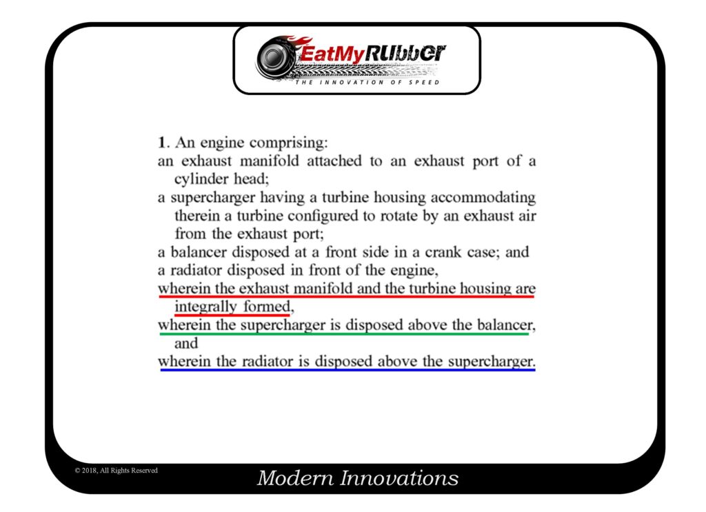
First, you have to get over the fact that the claim refers to a turbocharger as a supercharger; the written description clarifies the nomenclature. Next, you will notice that the claim lays out just a few of the engine components that will be found in all virtually all engines, specifically an exhaust manifold, a turbo, a balancer located at the front side of the crank case, a radiator in front of the engine. Finally, the claim defines, via the “wherein” clauses, the arguably unique relations that resulted in the issuance of the patent. Specifically:
(1) The exhaust manifold and the turbo housing are integrally formed;
(2) The turbo is located above the balancer; and
(3) The radiator is above the turbo.
So, you will notice that items (2) and (3) are relatively broad, meaning that it would be relatively easy to install a turbo and have it meet these location relationships. It is item (1) that is the real limitation in the claim, namely that the turbo housing is integrally formed with the exhaust manifold. If you are in the aftermarket turbo market, inevitably you will be looking for ways to save space, and one of the most logical ways is to directly incorporate the turbo housing into the exhaust manifold. Sure, this “integrally formed” limitation can seem pretty narrow, but let’s face it – if a big OEM is going to incorporate a turbo, this is a logical way for them to save space and engineer a system for the best overall performance. Therefore, this may be a very valuable patent for Suzuki, after all, while one can argue whether or not such incorporation is a pain in the ass for servicing, it defines something unique to Suzuki and sets up barriers for the competition.
The patent originates from a Japanese patent application, which are notorious for not providing a lot of information regarding why these claim limitations provide meaningful benefits. I reviewed the patent office file wrapper and was surprised to see that the claims were allowed exactly as they were originally proposed, which is very rare and is usually an indication that the applicant did not propose broad enough claims at the outset. This isn’t an unusual strategy when the desire is to get a patent issued quickly, but would usually be followed-up by filing a continuation patent application before the parent application issues, whereby the applicant pursues broader (think greedier) claims in the continuation application.
Interestingly, Suzuki did not file a continuation application, which tells me that they don’t view this “invention” as important to their business, or they just have a bad patent strategy. Now that the patent is issued without a continuation application filed, we would say that the family is closed (at least in the US) and now a competitor can more confidently design-around the issued claims. This is the reason the practice of keeping a family open is so important. As long as a family is open the applicant can amend claims in an attempt to cover what competitors have done to design-around the issued patent(s), provided there is support for such amendments within the original disclosure. Patent strategy is critically important, and these facts suggest that Suzuki is behind the times with their patent strategy and could use some proactive patent strategy counseling (give me a ring!).
The following is the Suzuki’s explanation of the benefits of this configuration:
When manufacturing the exhaust manifold by bending the pipes in this way, a space for securing a bending radius of the pipe is required due to an influence of a minimum bending radius of the pipe. Therefore, the supercharger should be attached with being spaced from the engine by a distance corresponding to the space. As a result, it is difficult to dispose the supercharger near the engine.
Also, since the supercharger is configured to compress the intake air by using the exhaust air of the engine, the heat is considerably generated during the driving. Particularly, when the components such as the radiator are provided in front of the engine, it is necessary to sufficiently secure a gap between the supercharger, which is a heat generation component, and the radiator, so that the vehicle is enlarged as a whole in the front-rear direction.
Therefore, in the illustrative embodiment, the exhaust manifold (manifold part 21) and the housing part 22 of the supercharger 2 are integrally formed by the casting, so that the exhaust manifold (housing main body 23) is made smaller, as compared to a configuration where the pipe is bent. Thereby, it is possible to dispose the supercharger 2 near the engine 1 (crank case 4). As a result, it is not necessary to secure a large radius, which is required when bending the pipe, so that it is possible to dispose the supercharger 2 without increasing the width of the engine 1 in the front-rear direction.
That is, in the illustrative embodiment, the supercharger 2 of which the exhaust manifold and the housing are integrally formed is adopted, so that it is possible to arrange a bending point of the manifold part 21 near the engine 1. Thereby, it is possible to dispose the supercharger 2 near the engine 1 and above the balancer 42. Further, since the bending point of the manifold part 21 is made small, a space is secured above the manifold part 21 and the radiator unit 6 (first radiator 60) is disposed in the corresponding space. By these configurations, it is possible to reduce the entire width of the engine 1 in the front-rear direction even though the engine has the radiator unit 6.
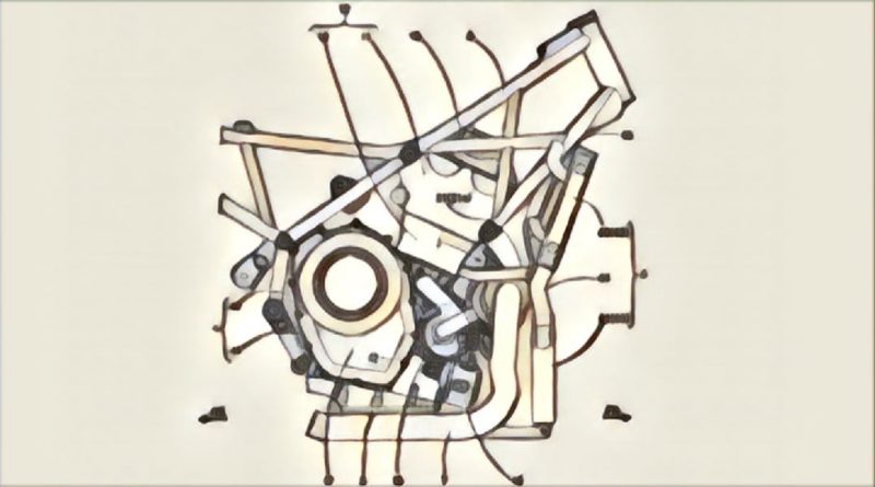
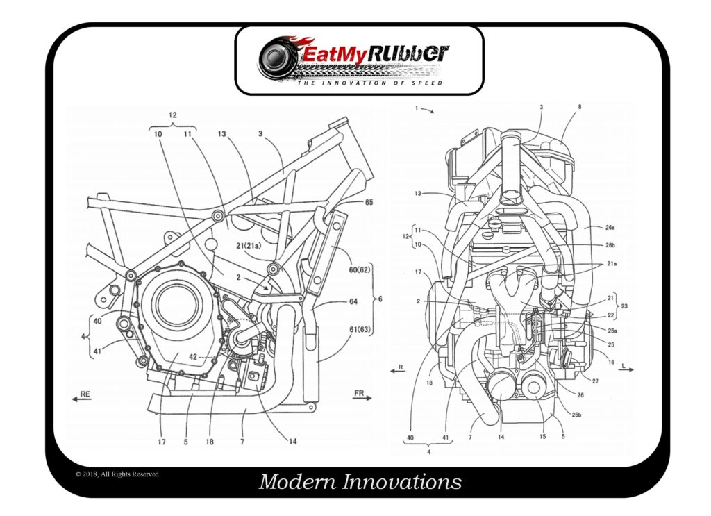
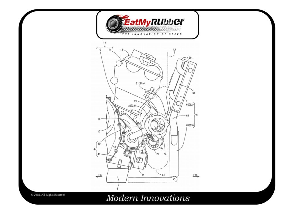
Subsequently, a layout of surrounding configurations of the supercharger and the engine is described with reference to FIGS. 2 and 3. FIG. 3 is a side view depicting a configuration around the supercharger in accordance with the illustrative embodiment.
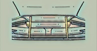
As shown in FIGS. 2 and 3, in the illustrative embodiment, the cylinder assembly 12 and the cylinder head cover 13 are inclined forward relative to the crank case 4, and a front end of the cylinder head cover 13 is positioned in front of the front surface of the crank case 4. Also, the radiator unit 6 is disposed with a slight gap forward from the front end of the cylinder head cover 13. The radiator unit 6 is disposed to extend from a lower end of the crank case 4 to a height of the cylinder head cover 13 in the substantially vertical direction.
In this way, a space S1 extending vertically is formed in the gap between the engine 1 and the radiator unit 6, i.e., among the front of the crank case 4, the lower of the cylinder assembly 12 and the radiator unit 6. In the illustrative embodiment, the housing main body 23 (the manifold part 21 and the housing part 22) is integrally formed by the casting, so that the width of the manifold part 21 in the front-rear direction is made as small as possible and the housing part 22 is thus disposed close to the crank case 4. For this reason, it is possible to dispose the supercharger 2 near the crank case 4 in the limited space S1, so that it is possible to reduce the entire width of the engine 1 in the front-rear direction.
Also, the supercharger 2 is disposed above the balancer 42 and below the first radiator 60. The supercharger 2 is disposed between the balancer 42 and the radiator unit 6 (particularly, the first radiator 60), so that it is possible to effectively utilize a space in front of the crank case 4. In particular, the supercharger 2 is disposed above the balancer 42, so that it is possible to secure a height ranging from a ground to the supercharger 2. Therefore, even when foreign matter or water is hoisted by wheels (not shown) during the traveling, it is possible to prevent the foreign matter or water from being directly attached to the supercharger 2. Thereby, it is possible to prevent a situation where when the water or the like is attached to the supercharger 2, the supercharger 2 is rapidly cooled and the constitutional components (diverse housings and the waste gate valve 27) of the supercharger 2 is thus deformed because the supercharger 2 is a heat generation component, as described above. Also, the height ranging from the ground to the supercharger 2 is secured, so that the supercharger 2 is difficult to be submerged into the water and anti-submergence of the supercharger 2 is improved.
Also, the supercharger 2 is disposed above the balancer 42 (lower case 41), so that it is possible to use an own weight of the oil when returning the oil supplied to the bearing housing 25 to the lower case 41. For this reason, it is not necessary to separately provide a dedicated oil pump so as to return the oil to the crank case 4, so that it is possible to simplify the configuration.
Also, the electric fan 65 is disposed above the manifold part 21, so that the electric fan 65 can be disposed with being spaced from the manifold part 21. The manifold part 21 is a heat generation part. However, as described above, the electric fan 65 has the fan formed of the resin material. Therefore, the gap is secured between the manifold part 21 and the electric fan 65, so that it is possible to suppress a direct influence of heat from the supercharger 2 on the electric fan 65.
Also, the first radiator 60 is disposed above the manifold part 21 and below the cylinder head cover 13. More specifically, a lower end of the first radiator 60 is located at a higher position than a lower end of the manifold part 21 (the connection part between the manifold part 21 and the housing part 22), and an upper end of the first radiator 60 is located at a lower position than an upper end of the cylinder head cover 13. For this reason, it is possible to dispose the first radiator 60 in a limited space between the manifold part 21 and the cylinder head cover 13, so that it is possible to effectively utilize the space. In particular, it is possible to dispose the radiator unit 6 without increasing an entire height of the engine 1.
Also, regarding the housing main body 23, the manifold part 21 is connected above the housing part 22. For this reason, it is not necessary to extend the manifold part 21 downward, and it is possible to secure a space below the housing part 22. As a result, the oil cooler 14 and the oil filter 15 are disposed in the empty space, so that the space is effectively utilized.
Further, the manifold part 21 (the pair of pipes 21 a) is positioned at the rear of a front surface (a dashed-two dotted line L1 in FIG. 3) of the housing part 22. In the illustrative embodiment, since the housing main body 23 is integrally formed by the casting, it is possible to shorten the lengths of the pipes 21 a, as compared to a configuration where the pipes are bent. Therefore, it is possible to reduce a protrusion amount of the manifold part 21 in the front-rear direction. Also, the housing part 22 is provided below the manifold part 21, so that it is possible to bring the entire supercharger 2 close to the crank case 4-side. For this reason, it is possible to reduce the entire width of the engine 1 in the front-rear direction.
As described above, according to the illustrative embodiment, the exhaust manifold (manifold part 21) and the turbine housing (housing part 22) are integrally formed by the casting, so that it is possible to design the shape of the exhaust manifold (housing main body 23) smaller, as compared to a configuration where the pipes are bent. For this reason, it is possible to dispose the supercharger 2 near the engine 1. Also, as the shape of the exhaust manifold is made smaller, it is possible to dispose the radiator unit 6 (first radiator 60) near the engine 1-side above the supercharger 2. By these configurations, it is possible to reduce the entire width of the engine 1 in the front-rear direction even though the engine has the radiator unit 6. In this way, since it is possible to secure a degree of freedom as to the shape of the housing main body 23, it is possible to dispose the supercharger 2 without enlarging the engine 1, as compared to a configuration where the exhaust manifold and the turbine housing are separately formed. Also, the number of components is reduced, so that it is possible to simply perform a mounting operation.
Interesting patent, and hopefully you learned something.
Can’t afford a turbocharger kit for your bike, consider this cheaper alternative.
Dave Dawsey – The Turbo Invention Attorney
PS – please follow me on Twitter (@EatMyRubberTech) and sign-up to receive posts via email.