Thankfully Someone is Thinking About Your Bike’s Engine When It Isn’t Running
It is hard to believe it has been 5 months since I wrote the post “What Suzuki Considers Important When Turbocharging a Motorcycle.” Boy how time flies. Last week a Suzuki patent application published further illustrating their R&D commitment to turbo bikes. (Browse Suzuki motorcycle parts on Amazon)
Have you ever thought about what goes on in an engine after you turn it off? What about the effect your bike is leaning on the kick stand has on the engine components?
As an engineer, gearhead, and patent attorney, I think about weird stuff like this, but have to admit that not once have I considered the implications of the tilt of the engine associated with the kick stand. Luckily the engineers in Suzuki’s R&D department thing about these things.
If you have read this far, you are a gearhead and will appreciate letting the patent application explain the rest of the story. The patent application published as US Pub. No. 20180313249 and explains:
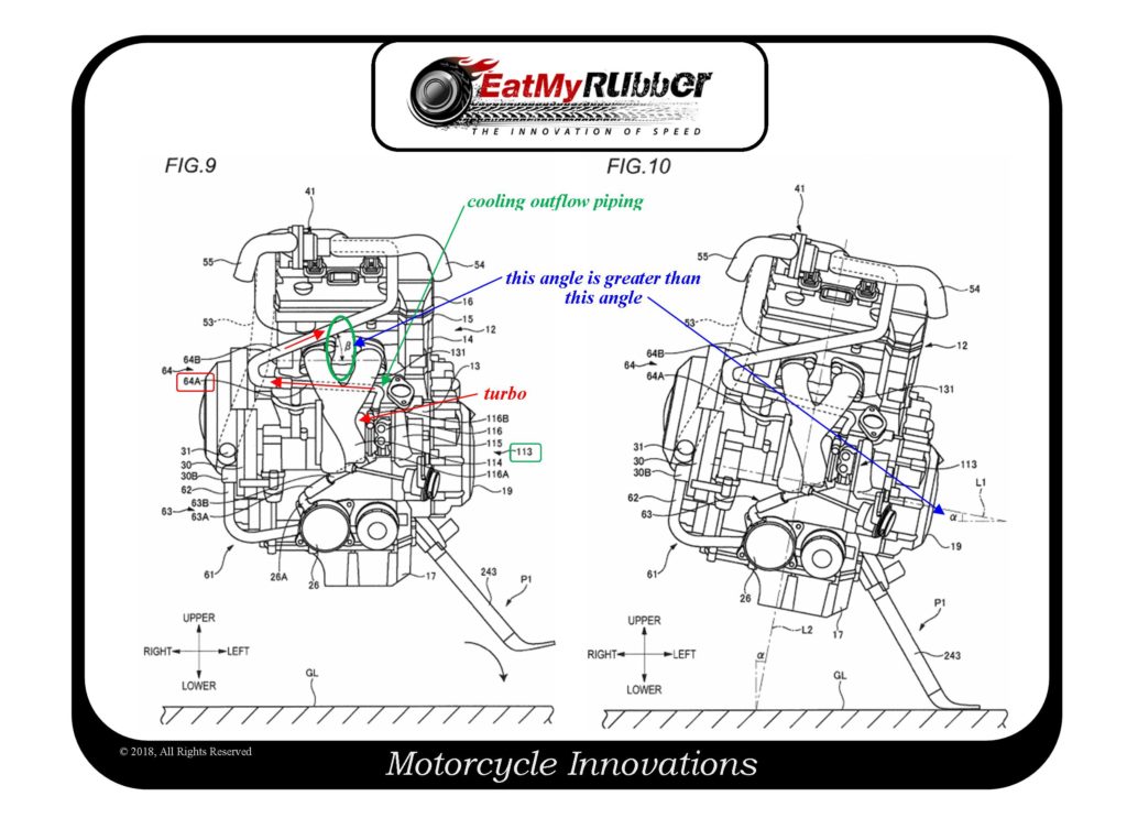
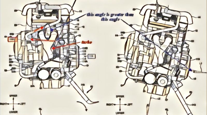
[0111] Herein, an example where the supercharger 113 is cooled when the engine 12 is stopped and the motorcycle 1 is stopped using the side stand 243 is described with reference to FIGS. 9 and 10. As described above, when the side stand 243 is displaced to the using position P1 and is thus grounded to the ground surface GL (with the side stand 243 being used), the motorcycle 1 is inclined toward the side stand 243-side (left-side).
[0112] In a state where the motorcycle is kept horizontal, the supercharger outlet pipe 64A of the outflow piping 64 is slightly inclined upward from the left toward the right (refer to FIG. 9). For this reason, when the motorcycle 1 is inclined toward the side stand 243-side, the left side (upstream side) of the supercharger outlet pipe 64A descends and the right side (downstream side) ascends (refer to FIG. 10). That is, the gradient (inclined angle) of the supercharger outlet pipe 64A increases. On the other hand, at the state where the motorcycle is kept horizontal, the tilted hose 64B of the outflow piping 64 is inclined upward from the right toward the left (refer to FIG. 9). For this reason, when the motorcycle 1 is inclined toward the side stand 243-side, the right side (upstream side) of the tilted hose 64B ascends and the left side (downstream side) descends. Herein, as described above, since the pipe angle .beta. is greater than the vehicle stop angle .alpha., the right side of the tilted hose 64B does not descend beyond the left side thereof. That is, the tilted hose 64B is always kept at the inclined posture in which it is inclined upward from the upstream side toward the downstream side (refer to FIG. 10).
[0113] According to the motorcycle 1 of the first illustrative embodiment, the outflow piping 64 (the supercharger outlet pipe 64A and the tilted hose 64B) is provided to have the upward gradient from the upstream side toward the downstream side at the state where the motorcycle 1 is stopped using the side stand 243 (the motorcycle 1 is inclined toward the side stand 243-side). For example, when the water pump 30 stops as the engine 12 stops, the cooling water flowing through the cooling piping 61 also stops. Thereafter, the cooling water is heated at the supercharger 113, thereby generating water vapor. Since the outflow piping 64 takes the inclined posture above the supercharger 113, the generated water vapor smoothly moves downstream through the outflow piping 64. Then, the cooling water upstream of the supercharger 113 is pushed toward the supercharger 113 by a pressure equilibrium action between the supercharger 113 and the cooling piping 61. Thereby, the cooling water is supplied to the oil cooler 26 and the supercharger 113, so that even after the engine 12 stops, it is possible to continuously cool the oil cooler 26 and the supercharger 113. Also, it is possible to prevent seizing of a bearing (not shown) configured to pivotally support the crankshaft and deterioration of the engine oil.
[0114] Also, the connection part (the second cooling water inlet 45) between the tilted hose 64B (the outflow piping 64) and the cooling water flow control unit 41 is provided at the side stand 243-side (left side). According to this configuration, the cooling water flow control unit 41 is located at the highest position with the motorcycle 1 being inclined toward the side stand 243-side. Then, the water vapor of the cooling water is smoothly pushed from the outflow piping 64 (the tilted hose 64B) to the cooling water flow control unit 41 through the second cooling water inlet 45. Thereby, it is possible to supply the cooling water in the cooling water flow control unit 41 and the like to the supercharger 113 by the pressure equilibrium action between the supercharger 113 and the cooling piping 61.
[0115] The outflow piping 64 is connected to the cooling water flow control unit 41 (circulation path) located at the position higher than the oil cooler 26 and the supercharger 114. The cooling water flow control unit 41 is disposed at the highest position in the flowing path of the cooling water. According to this configuration, since the outflow piping 64 (the tilted hose 64B) is connected at the highest position in the circulation structure of the cooling water (supercharger cooling water circulation structure), the water vapor of the cooling water can smoothly move up without being disturbed. Also, the cooling water used for cooling the engine 12, the oil cooler 26, the supercharger 113 and the like is collected to the cooling water flow control unit 41 and is then cooled by the radiator 33. Thereby, it is possible to stabilize the temperature of the cooling water, which is to pass through the radiator 33 and to be supplied to the engine 12. In the meantime, the outflow piping 64 is connected to the cooling water flow control unit 41. However, the disclosure is not limited thereto. For example, the outflow piping 64 may also be connected to the water jacket of the engine 12 and other piping (a hose, a pipe, a branched piping and the like), which serve as the circulation path.
[0116] According to the motorcycle 1 of the first illustrative embodiment, the oil cooler (engine oil) is cooled by the cooling water supplied from the water pump 30 via the inflow piping 60. Thereby, it is possible to sufficiently cool the engine oil, which is to be supplied from the oil cooler 26 to the engine 12, by using the cooling water that is not used for other cooling. For example, the cooled engine oil is supplied to the engine 12, so that it is possible to suppress seizing of a bearing configured to pivotally support the crankshaft, and the like. Also, the water pump 30, the oil cooler 26 and the supercharger 113 are connected in series by the cooling piping 61. Thereby, it is possible to simplify the circulation structure (the cooling system of the engine unit 11) of the cooling water.
[0117] Also, according to the motorcycle 1 of the illustrative embodiment, since the supercharger 113 is disposed in the vicinity of (just above) the upper of the oil cooler 26, it is possible to shorten a length of the connection piping 63. Thereby, it is possible to save the weight and cost of the motorcycle 1.
[0118] In the meantime, for example, when the water pump 30 stops as the engine 12 stops, the cooling water flowing through the cooling piping 61 also stops. Thereafter, the cooling water is heated at the supercharger 113, thereby generating water vapor. Regarding this, in the illustrative embodiment, the outflow piping 64 is connected to the cooling water flow control unit 41 (circulation path) positioned above the oil cooler 26 and the supercharger 113. The cooling water flow control unit 41 is disposed at the highest position in the flowing path of the cooling water. For this reason, the generated water vapor smoothly moves downstream through the outflow piping 64. Then, the cooling water upstream of the supercharger 113 is pushed toward the supercharger 113 by a pressure equilibrium action between the supercharger 113 and the cooling piping 61. Thereby, the cooling water is supplied to the oil cooler 26 and the supercharger 113, so that even after the engine 12 stops, it is possible to continuously cool the oil cooler 26 and the supercharger 113. Also, it is possible to prevent seizing of a bearing (not shown) configured to pivotally support the crankshaft and deterioration of the engine oil.
[0119] Subsequently, the motorcycle 1 in accordance with a second illustrative embodiment is described with reference to FIG. 11. FIG. 11 is a front view depicting the engine 12 and the cooling piping 70 with the motorcycle being stopped using the side stand 243. Meanwhile, in below descriptions, the same configurations as the first illustrative embodiment are denoted with the same reference numerals and the descriptions thereof are omitted.
[0120] The motorcycle 1 of the first illustrative embodiment has the cooling piping 61 configured to connect in series the oil cooler 26 and the supercharger 113. However, the motorcycle 1 of the second illustrative embodiment has the cooling piping 70 configured to connect in parallel the oil cooler 26 and the supercharger 113.
This is another example of the interesting things you can learn from patent applications. So, if you are adding an aftermarket turbo to your bike, this is something you should be thinking about as you are doing the plumbing.
Dave Dawsey – The Turbo Invention Attorney
PS – please follow me on Twitter (@EatMyRubberTech) and sign-up to receive posts via email.